Zdá se, že používáte prohlížeč, který nepodporuje dnešní standard pro zobrazování obsahu na webu. To může způsobit, že některé části webu nemusí fungovat správně. Doporučujeme Vám prohlížeč aktualizovat nebo si stáhnout takový, který dnešní standard splňuje.

Aktualizovat

Nastavení cookies

"Cookies" jsou malé soubory prohlížeče, které nám umožňují dočasně ukládat informace ohledně vašeho zařízení a vás, jako uživatele, výhradně v době, kdy procházíte web LICON. Tyto soubory nám pomáhají získat informace o návštěvnosti a chování uživatelů, na základě kterých web průběžně vylepšujeme.

Zpět na seznam

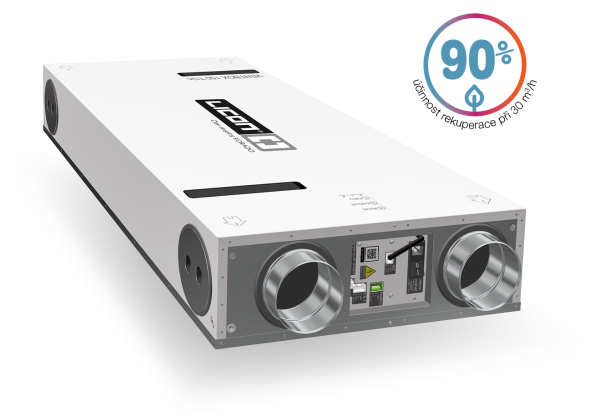
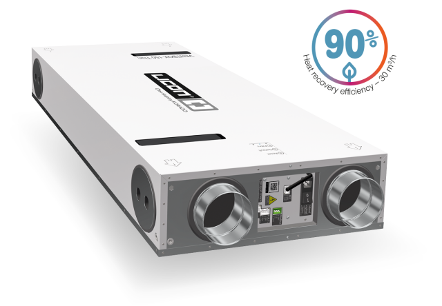
VENTBOX 150 Thin

Apartments up to 100 m²

The VENTBOX 150 Thin central heat recovery system provides a revolutionary and user-friendly solution for optimising the air quality in your home. This modern unit is designed with the latest technology and engineering developments in mind to provide optimum performance and comfort for residential and smaller family homes. Features of this unit include air purification from allergens and pollen, efficient exhaust air and water vapour extraction, low energy consumption, reduced excessive CO2 and can be controlled via a web interface. With the VENTBOX 150 Thin you can be sure that your home will always have fresh and healthy air.

  • Optimum version
This is an innovative and powerful heat recovery unit designed to optimally achieve maximum performance while ensuring economic efficiency. The unit is equipped with all the necessary technical equipment to ensure efficient operation and optimization of all performance parameters.
  • Premium version

The unit is additionally equipped with unrivalled motors with constant flow function. These unique fans compensate for pressure losses (e.g. in case of flow blockage at the inlet). With these premium EC motors, the unit can operate more efficiently and economically; this has a positive effect on the overall dynamics and also the economy when using the heat recovery system. Compensation for changes in pressure losses in the system, e.g. when the filters gradually become clogged. Ensuring uniform ventilation and high efficiency of heat recovery. The unit is more sophisticated.


  • Efektivní odvod odpadního vzduchu
  • Na strop, stěnu nebo podlahu
  • Nízká spotřeba
Recommended area up to 100 m²
Energy class A
Installation option Floor mounting, under the ceiling, wall mounting / left or right variant
Dimensions (h × w × d) 192 × 593 × 1 248 mm
Weight [kg] 20 kg
Voltage 230 V AC/50 Hz
Electric current without preheating [A] 0,3 A
Electric current including preheating [A] 3,7 A
Max. input power of the unit without preheating [W] 51 W
Max. preheating input power [W] 1 024 W
IP coverage 30
Air flow [m³/h] 30–150 m³/h
Maximum airflow in BOOST setting [m³/h] 200 m³/h
Reference air flow [m³/h] 105 m³/h
Displacement pressure [Pa] 50–350 Pa
Acoustic energy LWA [m³/h/Pa/dB] 105 m³/h/50 Pa/46,9 dB
Heat transfer efficiency / Flow rate 78 %/150 m³/h; 83 %/105 m³/h; 88 %/50 m³/h
Electrical input (without preheating) 55 W/150 m³/h; 29 W/105 m³/h; 17 W/50 m³/h
∅ of the connection necks [mm] 125 mm
Type of pipe for condensate drainage HT DN 32 mm
Specific power consumption SPI* W/m³/h 0,29 W/at reference airflow 105 m3/h and disposition pressure of 50 Pa
Max. number of all sensors (CO2 / RH / RADON …) 9
Connector for fire sensor or EPS connection Yes
Automatic frost protection Yes
Bypass function (exchanger bypass) Yes
Shock ventilation Yes
Weekly time mode Yes
Measuring energy consumption Yes
Modbus TCP/IP communication Yes
Modbus RTU communication Yes
Analogue input 2
Digital input 1
Filter clogging indicator based on time interval Yes
Filter clogging indicator based on filter pressure drop Premium version 
Filters supply/exhaust (% of particles captured in a given filter class) Optimum version M5 ePM10 55 % (F7 optional)
Filters supply//exhaust (% of particles captured in a given filter class) Premium version  F7 ePM1 70 %
Enthalpy counterflow heat exchanger ERV
The enthalpy counterflow heat exchanger is an optional part of the heat recovery system which, in addition to heat recovery, also allows moisture recovery, thus supporting the maintenance of optimal indoor air humidity and thus improving the user comfort of apartments and residential buildings. These systems bring many benefits, including energy efficiency, reduced heating costs, and improved indoor air quality.
Working principle of the counterflow exchanger

princip-fungovani-s-ent-vymenikem 150

Main features and benefits

Heat exchange – an enthalpy heat exchanger ERV allows heat energy to be transferred from warmer exhaust air to cooler outdoor air, thereby increasing the temperature of the air entering the building in winter. This helps to reduce heating costs because the fresh air is heated passively during the exchange.
 
Moisture exchange – in addition to heat, the enthalpy heat exchanger allows moisture transfer. This is important for maintaining optimum humidity indoors. The moisture in the exhaust air is transferred
to the supply air, which can be useful in areas with extreme climatic conditions.
 
Reduction of losses and pollution – the enthalpy heat exchanger also serves to separate the supply and extract air, preventing the transfer of pollution, dirt and unwanted odours from the outside into
the building. This improves the indoor air quality
 
The enthalpy heat exchanger can be ordered separately or later; after a very simple installation, the entire unit is upgraded with advanced technology.
Specifications with enthalpy exchanger  VENTBOX 150 Thin Optimum and Premium  version
Weight of the entire unit 21,5 kg
Energy class A
Heat transfer
efficiency / Flow rate
70 %/150 m³/h
74 %/105 m³/h
82 %/50 m³/h
Moisture transfer
efficiency / Flow rate
48 %/150 m³/h
53 %/105 m³/h
63 %/50 m³/h
 
Výměník v jednotce
 
Order Code for the Enthalpy Exchanger for the VENTBOX 150 Thin:  P-019
Pleasant indoor climate during both summer and winter
What happens in summer? How does it work in winter?
Relatively humid air seems warmer in summer than it actually is, so
heat and moisture are removed from the warm and humid outside air
before fresh air is brought into the house.
In winter, valuable heat is recovered and remains inside. With humidity
recuperation, more of the necessary moisture is transferred to the
dry outside air.
co-se-deje-v-lete-a-v-zime

VENTBOX COMPONENTS, FILTERS, CONTROL, BY-PASS

VENTBOX components  

rozpad-jednotky 150

Basic specifications
1 VENTBOX 150 Thin ventilation unit with white galvanised sheet metal on one side (casing not removable)
2 casing of the device
3 air duct connection necks ∅ 125 mm
4 connection caps
5 outlet for condensate discharge
6 unit body
7 bypass damper including actuator
8 plate counterflow heat exchanger ( HRV/ERV) 
9 fixing rail                                                                                 
10 fans with efficient EC motor
11 control electronics and power supply of the unit (2× analog inputs, 1× digital input, connector for connecting fire sensor or electrical fire alarm system (EPS), temperature sensors)
12 control and information panel
13 control electronics cover
14 air filters
15 filter closing caps
16 fan cover
17 heat exchanger cover
18 preheating cover
19 preheating
20 wedge for directing the airflow (when using side outlets)
 230 V mains power cable
Basic software functions
• automatic frost protection'
• bypass function (exchanger bypass)
• control via a web interface 
• weekly time mode
• Modbus RTU communication
• measuring energy consumption
• BOOST shock ventilation
Optional specification
• enthalpy counterflow heat exchanger 
• continuous variable manual control
• CO2 sensors
• relative humidity (RH) sensor
• radon concentration sensors
• TVOC and HCHO (volatile substances and formaldehyde) sensor
• filter clogging indicator based on filter pressure drop
• filter clogging indicator based on time interval
• INPUT filters (Optimum) F7 (ePM1 70 %)* – pollen
• EXHAUST filters (Optimum) F7 (ePM1 70 %)* – pollen
• insulation box (place the unit in a place with lower temperature)
* the figure in (%) tells how many particles in a given filter class the filter “captures”
FILTERS 
• Filtration class M5 – inlet  (Optimum version only) – 204 × 127 × 29 mm, ePM10 50 %
• Filtration class M5 - exhaust (Optimum version only) – 204 × 127 × 29 mm, ePM10 50 %
• Filtration class F7 inlet – 204 × 127 × 29 mm, ePM1 70 %
• Filtration class F7 exhaust – 204 × 127 × 29 mm, ePM1 70 %
 

filtry

CONTROL
iphone 150   Unit control via web interface
The home screen is used to view information, control and set up the VENTBOX 150 Thin. The middle part displays the current power of the
unit; information and status icons are below, then the current values are measured by the room sensors used by the unit (provided that the sensors are connected to the heat recovery unit). The lower part contains buttons for operating and setting the heat recovery unit.
 
  Control and information panel
The VENTBOX 150 Thin can normally be operated via the web interface, but all basic service operations can also be performed manually
(by pressing the appropriate button) on the control panel located on the front of the device:

R a short press of the button to perform a reboot, which preserves all user and service settings of the device.ovladaci-panel 150
D a longer press of the button (5 s) to enter the factory settings, where the ventilation unit runs permanently at reduced power.
At the same time, all user settings will be lost, including weekly program settings and network connections if previously made. The ventilation unit goes back to AP mode including the login password set by the manufacturer.
F press the button (2 s) to set the new filter change interval. Use this only for filter changes!

Information LED
• green – power – flashing – connected to power (Standby mode), lit – device in operation
• blue – filters – lit or flashing request for filter change
• red – error – must check “Error messages”


ipad 150
 

Režim by-pass
Jednou z klíčových součástí centrálních rekuperačních jednotek VENTBOX je režim by-pass. Tento režim je umožněn pomocí by-passové klapky, která je opatřena servopohonem. V případě manuální nebo automatické aktivace a na základě definovaných teplot ve webovém rozhraní, umožňuje by-passová klapka obtok tepleného výměníku. Odtahovaný vzduchu z interiéru, je klapkou by-passu odkláněn tak, aby neprocházel přes výměník tepla, ale byl přímo odváděn ven z objektu a nepředával tepelnou energii venkovnímu vzduchu přiváděného do jednotky.
 
Režim by-pass je běžně využíván během letního provozu, především v nočních hodinách, kdy je venkovní vzduch přirozeně chladnější. Díky tomu je možné efektivně snížit teplotu vnitřních prostor bez potřeby aktivního chlazení. By-pass tak poskytuje účinný způsob, jak zajistit optimální tepelný komfort v interiéru během teplých letních měsíců.
Popis režimu by-pass
1. Princip režimu by-pass
– Při aktivním režimu je teplý vzduch z interiéru odveden přímo ven bez výměny tepla.
– Výměník tepla je tímto režimem za pomoci by-passové klapky vyřazen z funkce, čímž se zabraňuje nežádoucímu ohřevu přiváděného čerstvého vzduchu.
– Do interiéru je vháněn čerstvý chladný vzduch.
 
2. Podmínky aktivace
– By-pass je aktivován automaticky, pokud teplota v interiéru vystoupá nad požadovanou hodnotu nastavenou ve webovém rozhraní.
– Po dosažení požadované teploty v interiéru se režim by-pass deaktivuje a jednotka se přepne zpět na standardní rekuperační režim.
– Ve webovém rozhraní lze definovat i nejnižší možnou teplotu přiváděného vzduchu do interiéru.

3. Ochrana a filtrace
– Pro správnou funkci a ochranu systému je by-passová klapka doplněna by-passovým filtrem. Tento filtr chrání výměník tepla a motor před prachem a nečistotami, které mohou být obsaženy ve vzduchu odkloněném z interiéru, kdy nedochází proudění vzduchu přes standardní odtahový filtr.
– By-passový filtr je nezbytný k zajištění dlouhodobé spolehlivosti a efektivity rekuperační jednotky.
Výhody by-passové klapky
• energetická úspora – snižuje potřebu aktivního chlazení interiéru v létě
• zvýšení komfortu – umožňuje využití přirozeně chladnějšího venkovního vzduchu pro zlepšení vnitřního klimatu
User functions that you can control
•ventilation shutdown – Standby mode (unit is not disconnected from a power supply)
• switching between automatic and manual mode (A/M)
• one-time reduction of ventilation power when leaving the building (holiday)
• short-term increase of ventilation intensity (BOOST mode)
• manual bypass flap switching (summer only)
• user device settingsí 

iPhone-by-pass-150


VENTILATION PERFORMANCE

vetraci-vykon-tabulka 150

VENTBOX 150 Optimum – available ventilation capacity


vetraci-vykon-graf 150

ACOUSTIC PARAMETERS
Noise emitted from the unit to the surroundings according to EN ISO 9614-2
hluk-z-jednotky-do-okoli 150
 
Noise emitted into the duct according to EN ISO 5136 – at the discharge to the pipe
hluk-na-vytlaku-do-potrubi 150
 
Noise emitted from the unit into the duct (according to EN ISO 5136) – for suction into the duct
hluk-na-sani-do-potrubi 150

REQUIREMENTS FOR OTHER PROFESSIONS 

   
Electrical requirements
Mandatory preparation
Fixed power cables 3×2.5 with circuit breaker 16 A char. B from the switchboard to the heat recovery unit
• Terminate with an AC 230 V / 50 Hz socket no further than 1 m from the power socket of the heat recovery unit (the power socket of the heat recovery unit is located between the necks facing the interior).
• Marking of the circuit breaker with the label “heat recovery”.
• Do not block – bulk remote control!
 
Optional preparation
UTP cable from the home Wi-fi router to the heat recovery unit
• Terminate with RJ 45 socket at the location of the heat recovery unit. This is used only in case of a weak Wi-fi signal, for possible connection of a Wi-fi router, and for Wi-fi signal amplification (it is
not used for physical connection of the heat recovery unit).
 
Intensive exhaust buttons “WC, Bathroom, Kitchen”
• Bring UTP cable or J-Y(ST)Y 2×2×0.8 to all rooms with exhaust requirement (WC, bathroom, kitchen and other optional rooms).
• Connect all wires from the intensive exhaust buttons in parallel and connect them to the recovery unit.


• Terminate with a free cable with a reserve of min. 2 m, not farther than 0.5 m from the data terminal of the heat recovery unit and mark “WC button, Bathroom, Kitchen”, etc.
• In the rooms, install a push button with a return to the original
position.
 
CO2 and HYG sensors and continuous control panel (P.R.T.)
• Bring UTP cable or J-Y(ST)Y 2×2×0.8 for sensors and P.R.T. to the required rooms, the wires must be connected in series according to the requirements of the technical design of the RS 485 bus –
sensors communicate using Modbus RTU!
• Terminate the cable with a margin of min. 2 m, at the furthest 0.5 m from the data terminal of the heat recovery unit (data terminals are always located between the necks facing the interior).

Recommendations
• The CO2 sensor for bedrooms or living rooms should be placed at the height of the switches.
• Humidity sensors for bathrooms should be placed on the wall 10 cm below the ceiling.
• Always leave a margin of at least 0.3 m on the continuous cables that connect the individual sensors in series.
 
ELECTRICAL CONNECTION   
 
 
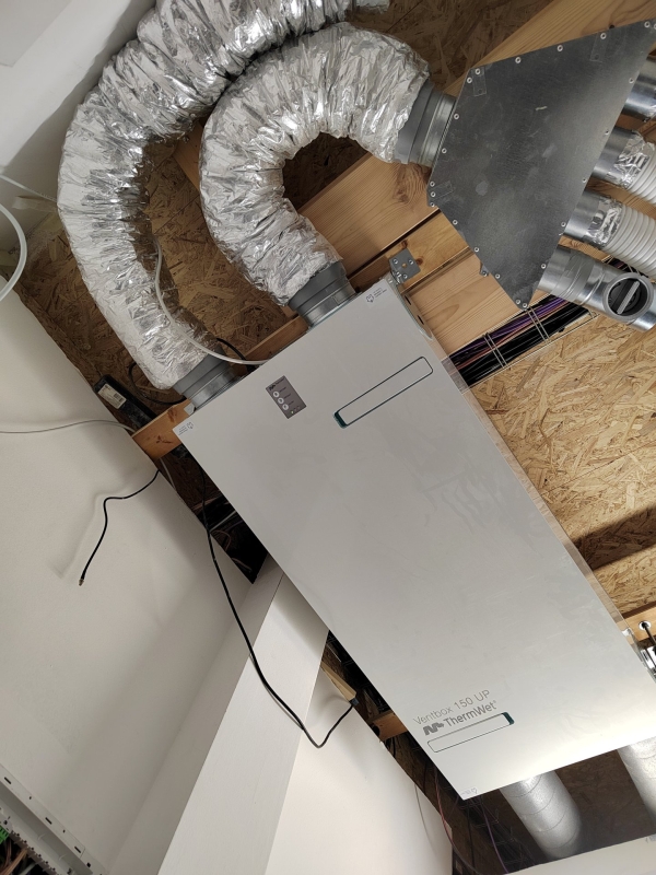
The electrical power connection of the VENTBOX 150 Thin is by means of a 1.5 metre power cable. All connector connections are located on the Control Panel, which is located between the interior necks. This is also the location of the unit’s main switch.
 
1 The unit’s main power switch with a socket for 230 V mains cable connection and FST 5× 20 10 A/250 V fuse
2 Modbus – connection of RH, CO2, TVOC, Radon sensors
3 P. R. T. analogue input for connection of external controller
4 AI2 analogue input
5 DI1 digital input for intensive exhaust buttons (bathroom, kitchen, WC)
6 Antenna used for wireless communication (connection to Wi-fi network).
 

Elektrické připojení

   
Requirements for water installation
Mandatory preparation
HT waste pipe – DN 32 mm
• Fit with a dry siphon and terminate it near the outlet of the condensate drain from the recovery unit (the condensate drain is always located between the outlet of the recovery unit that faces
the exterior).
• Keep in mind the required “inspection opening” and the possibility of disconnecting the recovery unit from the waste.
• It is necessary to ensure that the outlet has free flow, considering the overall gradient of the waste system (min. 3 %).
 
Vertical wall mounting
• Terminate the drain at least 20 cm below the bottom edge of the
recovery unit.
 
Horizontal mounting on the ceiling or floor
• Terminate the drain at least 5 cm from the bottom edge of the recovery unit.
Requirements for construction
Mandatory preparation
Air ducts ∅ 125 mm
• Supply air ducts according to the selected configuration of the rec. unit (right / left variant) and the location of air inlets (front / side outlet). Keep in mind the overall location of the heat recovery unit in the building (wall / drop ceiling / floor mounting).

Revision opening (min. 1 580 × 880 mm)
• Ensure sufficient space for installation and servicing with regard to the location of the heat recovery unit.
• The minimum required installation depth of the heat recovery unit is 220 mm!

Anchor holes
• With regard to the chosen mounting variant and it’s weight.

ASSEMBLY

Floor mounting  
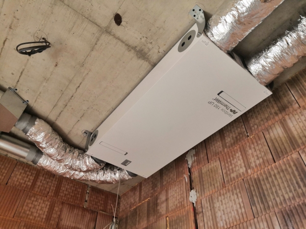
montaz-na-podlahu 150
1 socket 230 V AC / 50 Hz, or RJ 45
2 placement of wall mounting anchors – anchor holes 4× ∅ 10.5 mm,
mounting spacing 1 215 × 642 mm
3 optional side connections
4 inspection opening 1 580 × 880 mm
5 dry trap (recommended HL 138 DN 32)
 
Caution! Possible only with the right variant of the unit.


Installation under the ceiling  

montaz-pod-strop 150

1 socket 230 V AC / 50 Hz, or RJ 45
2 placement of wall mounting anchors – anchor holes
4× ∅ 10.5 mm, mounting spacing 1 215 × 642 mm
3 optional side connections
4 inspection opening 1 580 × 880 mm
5 dry trap (recommended HL 138 DN 32)
 
Caution! Possible only with the left variant of the unit.
 
Always place the unit on a level surface, and ensure it is correct orientation and overall gradient!
 
 
Wall mounting – left variant Wall mounting – right variant  

montaz-na-stenu-leva 150

montaz-na-stenu-prava 150
1 socket 230 V AC / 50 Hz, or RJ 4
2 placement of wall mounting anchors – anchor holes 4× ∅ 10.5 mm,
mounting spacing 1 298 × 536 mm
3 optional side connections
4 min. inspection opening 1 580 × 880 mm
5 dry trap (recommended HL 138 DN 32)


Dimensions in mm. Technical changes reserved.

legenda 150

  • Catalog VENTBOX 150 Thin
  • Advantages of Heat Recovery Units
  • Requirements for other professions
  • Current firmware  - Verze 2.440 Aktuální FIRMWARE
  • MODBUS modbus

ORDERING CODES

Example of ordering code: VB1-0150-TC-OHR
VENTBOX 150 Thin first generation with central heat exchanger, standard EC fans version Optimum, standard heat exchanger with right-hand side connection.

VENTBOX
Generation
 
Volume flow
 
Design
Heat recovery
unit type
 
Model / Type
Exchanger type 
Connection option 
V B
1
-
0150
-
T
C
-
O
H
R


Thin
C - centralized
 
O - Optimum
P- Premium 
H - standard
E - enthalpy
R - right
L - left

Kontaktujte nás

Pro více informací náš neváhejte kontaktovat
Odesláním formuláře souhlasíte se zpracováním osobních údajů.